Saturday, April 01, 2017
Tech cantilever
I've always been fascinated with the overlaps between eras in technology or style. The old era typically zooms out onto a long cantilever of extreme embellishment before the new undermines it.
Back in the late '60s I had a pretty good collection of old radios, bought at auction for $10-$15. The one I used most was the 1938 Philco that I've remade for Polistra's use....
 The Philco had good shortwave reception and wonderful tone quality.
The most 'cantilevered' radio in my collection was a 1929 RCA model RE-45, which attempted to create the PERFECT solution to the TRF problem. Tuned Radio Frequency sets had many stages of amplification, and all stages had to be tuned together. Most TRF receivers mounted five or six tuning capacitors on the same shaft, but this was unsatisfactory because each stage had its own slightly different bandpass curve. When you replaced a tube, you changed the characteristics of the stage, and you had to adjust various trimmer caps to get an approximate response. At best you could get precise tuning for one station. The RE-45 made it possible to compensate each stage's tuner for its own COMPLETE curve.
I finally found some tech info on this receiver, thanks to the infinitely valuable American Radio History website.
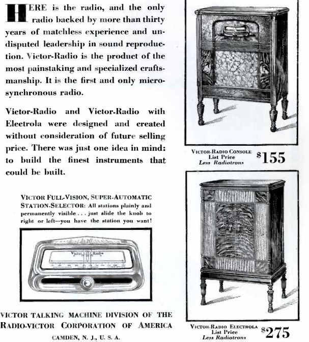
Front view from an ad:
 The tuner was simple to use. Pull up the knob slightly and slide it across the dial, or turn it to 'roll' the pointer more finely. Inside was a FANTASTIC piece of mechanism.
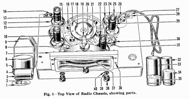
 Here's the 'micro-synchronous' part. When you slid the knob, it turned the big disk in the center of the chassis. The disk had about 30 little setscrews around the inner circumference (marked 18 on the diagram). Each setscrew pushed on a half-inch of the outer circumference, which was a flat leather belt. You thus shaped a tuning curve on one arc of the belt by adjusting the screws. As the main disk turned, the cam rollers (16) rode slightly out and in on the tuning curve. Each cam carried the base for one tuning capacitor.
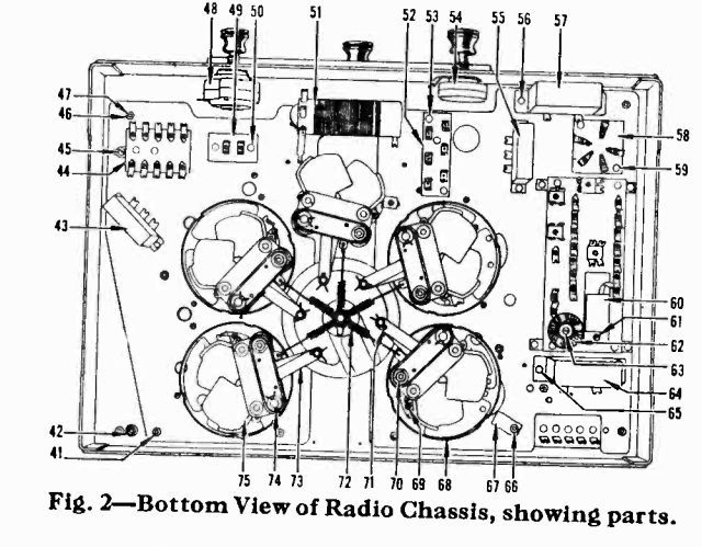
 Underneath, the same main disk pulled on a linkage that caused each of the five capacitors to move in a way that can't be described in words. I had to make a model...
 This shows the two sets of intermeshing plates (red and blue) being pushed in and out by the pusher linkage (green) which is 70 on the bottom diagram.
Now we add the action of the adjusting cams on top. The cams are moving the base of the capacitor (gray part) slightly up and down, which in turn changes the NET motion of the plates in an OPPOSITE way.
 This gave the repairman total control over the calibration of each stage to match its own peculiar tuning curve.
Did any repairman ever NEED or USE this level of control? I seriously doubt it. I tried adjusting those setscrews and didn't hear any meaningful difference. The radio received all nearby stations beautifully no matter how I adjusted the screws.
AND... the whole design was completely unnecessary in 1929, because superhet circuits were already practical and mature. RCA had produced the first commercial superhet in 1924. Superhets avoid the problem of matching tuning curves by reducing all incoming signals to the same intermediate frequency, which can then be detected and filtered uniformly with one curve.
 The Philco had good shortwave reception and wonderful tone quality.
The most 'cantilevered' radio in my collection was a 1929 RCA model RE-45, which attempted to create the PERFECT solution to the TRF problem. Tuned Radio Frequency sets had many stages of amplification, and all stages had to be tuned together. Most TRF receivers mounted five or six tuning capacitors on the same shaft, but this was unsatisfactory because each stage had its own slightly different bandpass curve. When you replaced a tube, you changed the characteristics of the stage, and you had to adjust various trimmer caps to get an approximate response. At best you could get precise tuning for one station. The RE-45 made it possible to compensate each stage's tuner for its own COMPLETE curve.
I finally found some tech info on this receiver, thanks to the infinitely valuable American Radio History website.
Front view from an ad:
 The tuner was simple to use. Pull up the knob slightly and slide it across the dial, or turn it to 'roll' the pointer more finely. Inside was a FANTASTIC piece of mechanism.
 Here's the 'micro-synchronous' part. When you slid the knob, it turned the big disk in the center of the chassis. The disk had about 30 little setscrews around the inner circumference (marked 18 on the diagram). Each setscrew pushed on a half-inch of the outer circumference, which was a flat leather belt. You thus shaped a tuning curve on one arc of the belt by adjusting the screws. As the main disk turned, the cam rollers (16) rode slightly out and in on the tuning curve. Each cam carried the base for one tuning capacitor.
 Underneath, the same main disk pulled on a linkage that caused each of the five capacitors to move in a way that can't be described in words. I had to make a model...
 This shows the two sets of intermeshing plates (red and blue) being pushed in and out by the pusher linkage (green) which is 70 on the bottom diagram.
Now we add the action of the adjusting cams on top. The cams are moving the base of the capacitor (gray part) slightly up and down, which in turn changes the NET motion of the plates in an OPPOSITE way.
 This gave the repairman total control over the calibration of each stage to match its own peculiar tuning curve.
Did any repairman ever NEED or USE this level of control? I seriously doubt it. I tried adjusting those setscrews and didn't hear any meaningful difference. The radio received all nearby stations beautifully no matter how I adjusted the screws.
AND... the whole design was completely unnecessary in 1929, because superhet circuits were already practical and mature. RCA had produced the first commercial superhet in 1924. Superhets avoid the problem of matching tuning curves by reducing all incoming signals to the same intermediate frequency, which can then be detected and filtered uniformly with one curve.
This gave the repairman total control over the calibration of each stage to match its own peculiar tuning curve.
Did any repairman ever NEED or USE this level of control? I seriously doubt it. I tried adjusting those setscrews and didn't hear any meaningful difference. The radio received all nearby stations beautifully no matter how I adjusted the screws.
AND... the whole design was completely unnecessary in 1929, because superhet circuits were already practical and mature. RCA had produced the first commercial superhet in 1924. Superhets avoid the problem of matching tuning curves by reducing all incoming signals to the same intermediate frequency, which can then be detected and filtered uniformly with one curve.Labels: Metrology
