Tuesday, June 14, 2016
1948 IC
We treat integrated circuits as a silicon-era development, and consider Intel 1958 to be the point of invention. Simply not true. The idea is MUCH older.
Looking for new ways to screw around with submini tubes, I bumped into this 1948 publication by National Bureau of Standards, which served for a long time as a national clearing house for inventions. Auditing and examining new developments, giving a boost to those that seemed likely to help national purposes. Gosbank for creativity.
The booklet is a survey of the new technologies of printed circuits and integrated circuits, which were just starting to make inroads in military uses and hearing aids. Manufacturers and experimenters were trying several methods, directly parallel to the traditional methods of art and printing.
Two of those methods have stood the test of time. Sputtering/electroplating mainly for silicon ICs, photoresist etching mainly for PC boards.
The first method in the book (painting) didn't go commercial and seems to have been lost. I hadn't heard of it before. It deserves another look.
= = = = =
Placing integration in its proper historical perspective:
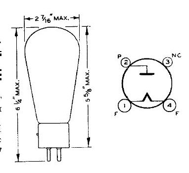
Here's the simplest single tube, a type 81 half-wave rectifier, developed around 1920. Just one active element in the bottle. Hot filament emits electrons, plate receives them. Current flow in one direction only. Checkvalve.
 = = = = =
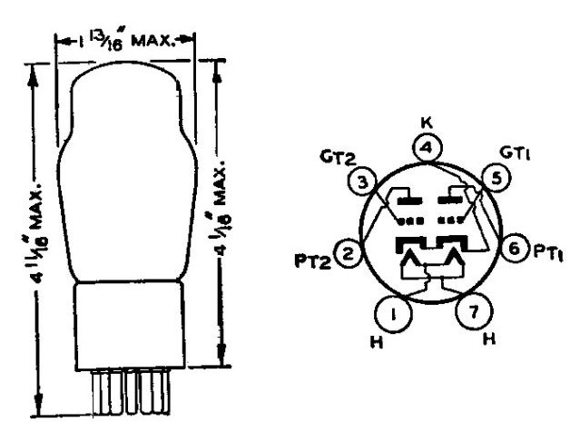
Around 1930, as radios got more complicated and crowded, tubemakers found ways to fit two or three active devices in one bottle. This type 53 contains two triode amplifier elements. This would likely have served as a class B push-pull amplifier stage. Because the two triodes were born together and mated for life, they are more likely to remain balanced and symmetrical than triodes in separate bottles. When each triode takes its half of the wave, each will handle it the same way. They heat up together, cool down together, and age together.
 = = = = =
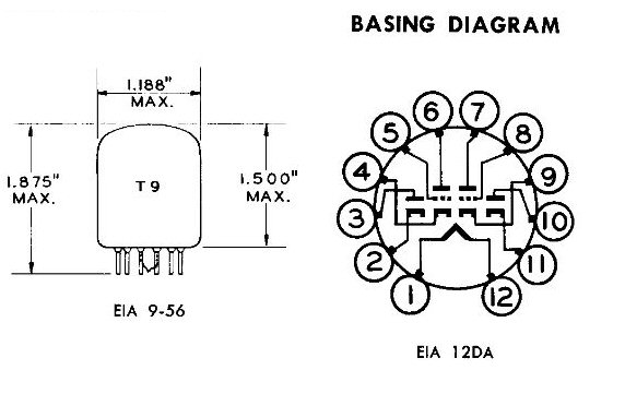
Toward the end of the tube era in the '60s, tube integration went wild. This 'Compactron' tube has two triodes and two diodes jammed into one fat bottle. Some Compactrons also included passive devices like resistors and capacitors, forming major sections of circuitry inside the bottle. Same advantages: save space, maintain original specs, age in unison.
 = = = = =
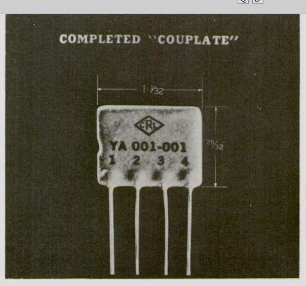
Getting closer to the 1958 IC: These modules made by Centralab were mentioned in the NBS booklet. They were common in hi-fis and TVs around 1960. No tube elements, just a network of resistors, capacitors and inductors printed and packaged together. These were especially useful in the high-frequency front end of a TV. At VHF frequencies every wire has a meaningful inductance and capacitance, so dimensions and shapes of wiring are critical. If you wire up separate components by hand, there's no way to standardize the dimensions and shapes; one little bump and the wire assumes a different curve with a different frequency response. Centralab modules kept the critical pieces standardized and immovable.
 = = = = =
Painting is the forgotten method. Semi-quoting from the booklet:
 Semiquoting again:
 = = = = =
Around 1930, as radios got more complicated and crowded, tubemakers found ways to fit two or three active devices in one bottle. This type 53 contains two triode amplifier elements. This would likely have served as a class B push-pull amplifier stage. Because the two triodes were born together and mated for life, they are more likely to remain balanced and symmetrical than triodes in separate bottles. When each triode takes its half of the wave, each will handle it the same way. They heat up together, cool down together, and age together.
 = = = = =
Toward the end of the tube era in the '60s, tube integration went wild. This 'Compactron' tube has two triodes and two diodes jammed into one fat bottle. Some Compactrons also included passive devices like resistors and capacitors, forming major sections of circuitry inside the bottle. Same advantages: save space, maintain original specs, age in unison.
 = = = = =
Getting closer to the 1958 IC: These modules made by Centralab were mentioned in the NBS booklet. They were common in hi-fis and TVs around 1960. No tube elements, just a network of resistors, capacitors and inductors printed and packaged together. These were especially useful in the high-frequency front end of a TV. At VHF frequencies every wire has a meaningful inductance and capacitance, so dimensions and shapes of wiring are critical. If you wire up separate components by hand, there's no way to standardize the dimensions and shapes; one little bump and the wire assumes a different curve with a different frequency response. Centralab modules kept the critical pieces standardized and immovable.
 = = = = =
Painting is the forgotten method. Semi-quoting from the booklet:
It is possible to purchase paints for conductors ready-mixed and applicable to any solid surface. NBS found that the preparation of conductor paints is not especially difficult though careful attention to quantity and quality is necessary if good adhesion to the base plate is desired.... There is no single paint formula which can be used to print resistors from one ohm to several hundred megohms. It is necessary to use several mixtures and vary the dimensions of the painted resistor. ... Capacitors can be incorporated directly in the base plate by a vitreous dielectric process.In other words, you could pretty much draw a schematic, with the C plates very close together, and let the glass base plate be the dielectric. = = = = = This picture shows some printed and some painted ckts:
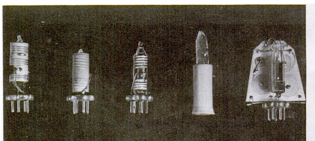
 Semiquoting again:
Five types of subminiature 132 mc radio transmitters using printed circuit techniques. All types are grid modulated and require only connection to a microphone and battery to operate. The oscillator ckts of the two units at the left are printed on the outer surface of a thin steatite cylinder housing the submini tube. The ckt of the center unit is PAINTED ON THE GLASS ENVELOPE of a 6K4 submini triode. Next is also painted on the glass envelope of the tube. [This one doesn't even look like a tube, let alone a ckt. Maybe the original picture was clearer?] On right, the same ckt painted on a flat steatite plate.Painted on the tube itself! Like an active tattoo! Intriguing. Incidentally, steatite is a fancy name for soapstone. It's generally ground up, formed into ceramics and baked, but this booklet doesn't say if the steatite is natural or ceramic'd. = = = = = Later: More detail on those NBS experiments, including schematics, in this 1947 issue of Radio-Craft.
Labels: Alternate universe
