
Wednesday, November 24, 2021
Powerful metaphor
Gunter Bechly is discussing the failure of 'missing links' in fossil records. Every major transition requires new genes and new proteins that couldn't have been generated gradually, and the gradual steps required by evolution are simply not there.
Bechly tells an evocative story. Experienced collectors learn where to find the good stuff, and learn what they are going to find in each of the suitable places. After you've been exploring and gathering long enough, you are never truly surprised. If you find an item that seems to be 'in between' two types or two layers, it will ultimately turn out to be in one layer or the other.
This immediately evoked an example.
I've been collecting old electronic stuff for 60 years. I'm not a serious collector because I don't display and classify stuff. After I've had fun with a device, I put it in the drawer or toss it.
In 2016 I bought an intriguing item on Ebay. It was advertised as an 'experimental transistor'. After closely examining it and running it through the usual transistor and tube tests, I decided it wasn't a transistor at all. It was experimental in the sense of being a prototype, but it was an ordinary subminiature vacuum tube, not a transistor or an in-between mashup. It also happens to look like a pre-Cambrian critter.
= = = = = START REPRINT:
I was idly browsing Ebay for Soviet transistors. Curious to see if the oldest ones looked similar to America's oldest transistors. Mostly yes. The Prince Albert shape of the early ones reminded me of my first live encounter with a transistor.....
Around 1958 I was fiddling with radios and electric stuff, and somehow picked up a catalog from Burstein Applebee. Spent hours dreaming through it. When parents visited an uncle in KC, I badgered them into letting me see the Burstein Applebee store in downtown KCMO. They dropped me off and went shopping somewhere else. I walked in and started wandering the aisles, marveling at all the receivers and antennas and tubes. The clerks were NOT happy to have an 8-year-old loose in the store. They herded me out, but not before I got a good look at THE REAL THING: A Raytheon CK722.
Does Ebay have CK722s? Plenty of them but that wasn't the most interesting item. Seller VintChip had a Raytheon 'experimental transistor' for $50.
Instant choice. Had to buy it.
Unpacking......
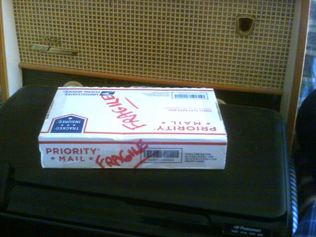 Vintchip does a good job of packing. Bubble wrap and tissue.
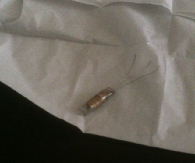 First impression: Printed label says Raytheon Experimental. Written in ink on one side is QF336, on the other side just the number 8. Presumption: This is serial number 8 of a set of experimental tubes denominated QF336.
Scanned both sides:
First impression: Printed label says Raytheon Experimental. Written in ink on one side is QF336, on the other side just the number 8. Presumption: This is serial number 8 of a set of experimental tubes denominated QF336.
Scanned both sides:
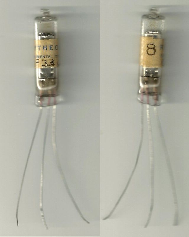 Looks very much like a miniature hearing-aid tube. Same glass outer envelope, same leads coming through the bottom sealed in glass, same 'can' surrounding the active part. Mini tubes were used in hearing aids briefly in the '50s. Hearing aids soon switched to transistors, but not because of size. Early transistors were about half the size of mini tubes and you needed two or three transistors to substitute for the typical tube. No real advantage. Batteries were the advantage. Tubes needed a large 1.5V filament batt and a large 45V plate batt, and used up the filament batt fast. Transistors used one 9V battery and drained it slowly.
= = = = =
Looks very much like a miniature hearing-aid tube. Same glass outer envelope, same leads coming through the bottom sealed in glass, same 'can' surrounding the active part. Mini tubes were used in hearing aids briefly in the '50s. Hearing aids soon switched to transistors, but not because of size. Early transistors were about half the size of mini tubes and you needed two or three transistors to substitute for the typical tube. No real advantage. Batteries were the advantage. Tubes needed a large 1.5V filament batt and a large 45V plate batt, and used up the filament batt fast. Transistors used one 9V battery and drained it slowly.
= = = = =
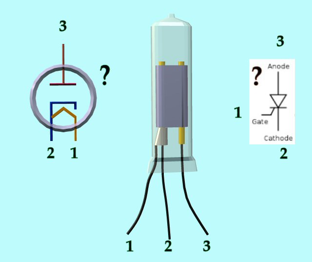 I can see the innards with a magnifier, but couldn't get a photo or scan. So I made a Poser version to illustrate. Two cylinders running through the can in parallel; one cylinder has one wire from it, and the other cylinder has a sort of sheath, with one wire centered and another wire Y-ing out of the sheath.
Innards STRONGLY suggest tube. The sheathed electrode is typical of a cathode with inner heater, with one side of heater tied to cathode. The opposite cylinder looks like the plate. Thinking tubey, this webpage shows a Sylvania experimental miniature thyratron, looking something like qf336, but the Sylvania has four terminals, which seems right. This critter has only three wires, which means it can't be a triode or a thyratron. Could it be a rectifier or a voltage-dependent switch?
One problem with tube assumption: the upper and lower ends of the can are closed by resin or epoxy. Tubes generally get too hot for epoxy.
Thinking solid-statey, the wire pattern reminds me of a thyristor or SCR schematic. Does this mean the schematic was meant to imitate this device? Probably not.
Well, let's try both assumptions. Using DVM, no connectedness shows between the terminals. On R scale and diode scale, just open ckt in both directions on all combinations of the three wires. About 7nF capacitance between terminals, which makes sense from the structure but doesn't mean anything. So this probably isn't solid-state, because even a blown or non-functional solid thing will show some kind of resistance.
I don't have any proper mini tubes for comparison. A large tube (35L6) shows about 40Ω across the filament, varying as the applied voltage slightly warms the heater. I don't know what to expect for a mini tube, but it would certainly be low enough to read easily. Two-digit ohms, not gonna look like open ckt.
= = = = =
Just for fun, trying the tube assumption in the simplest possible ckt for a rectifier. Battery across the filament, cathode to negative, 9V to the plate through a resistor, with voltmeter across the resistor to see if anything flows.
I can see the innards with a magnifier, but couldn't get a photo or scan. So I made a Poser version to illustrate. Two cylinders running through the can in parallel; one cylinder has one wire from it, and the other cylinder has a sort of sheath, with one wire centered and another wire Y-ing out of the sheath.
Innards STRONGLY suggest tube. The sheathed electrode is typical of a cathode with inner heater, with one side of heater tied to cathode. The opposite cylinder looks like the plate. Thinking tubey, this webpage shows a Sylvania experimental miniature thyratron, looking something like qf336, but the Sylvania has four terminals, which seems right. This critter has only three wires, which means it can't be a triode or a thyratron. Could it be a rectifier or a voltage-dependent switch?
One problem with tube assumption: the upper and lower ends of the can are closed by resin or epoxy. Tubes generally get too hot for epoxy.
Thinking solid-statey, the wire pattern reminds me of a thyristor or SCR schematic. Does this mean the schematic was meant to imitate this device? Probably not.
Well, let's try both assumptions. Using DVM, no connectedness shows between the terminals. On R scale and diode scale, just open ckt in both directions on all combinations of the three wires. About 7nF capacitance between terminals, which makes sense from the structure but doesn't mean anything. So this probably isn't solid-state, because even a blown or non-functional solid thing will show some kind of resistance.
I don't have any proper mini tubes for comparison. A large tube (35L6) shows about 40Ω across the filament, varying as the applied voltage slightly warms the heater. I don't know what to expect for a mini tube, but it would certainly be low enough to read easily. Two-digit ohms, not gonna look like open ckt.
= = = = =
Just for fun, trying the tube assumption in the simplest possible ckt for a rectifier. Battery across the filament, cathode to negative, 9V to the plate through a resistor, with voltmeter across the resistor to see if anything flows.
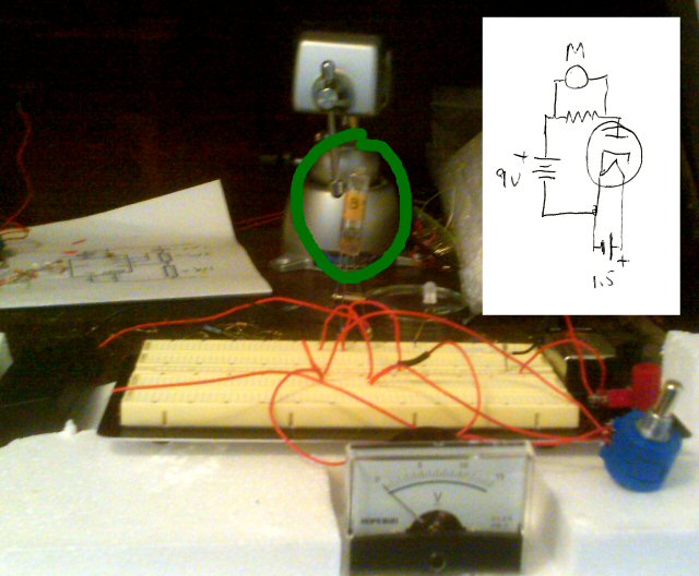 Nope. No heat from the filament, no flow at all.
Conclusion: This is probably a diode tube, and the filament is probably burned out.
= = = = = END REPRINT.
Honest paleontologists run through the same process. Excitement! This looks like a missing link! Darwin was right after all! Then do the chemical tests and look at it from various angles with microscopes and scanners.... Oops. It's a familiar item in a familiar layer after all. It was just divided in an unfamiliar way or petrified with an unfamiliar mineral.
Nope. No heat from the filament, no flow at all.
Conclusion: This is probably a diode tube, and the filament is probably burned out.
= = = = = END REPRINT.
Honest paleontologists run through the same process. Excitement! This looks like a missing link! Darwin was right after all! Then do the chemical tests and look at it from various angles with microscopes and scanners.... Oops. It's a familiar item in a familiar layer after all. It was just divided in an unfamiliar way or petrified with an unfamiliar mineral.

Vintchip does a good job of packing. Bubble wrap and tissue.
First impression: Printed label says Raytheon Experimental. Written in ink on one side is QF336, on the other side just the number 8. Presumption: This is serial number 8 of a set of experimental tubes denominated QF336.
Scanned both sides:
Looks very much like a miniature hearing-aid tube. Same glass outer envelope, same leads coming through the bottom sealed in glass, same 'can' surrounding the active part. Mini tubes were used in hearing aids briefly in the '50s. Hearing aids soon switched to transistors, but not because of size. Early transistors were about half the size of mini tubes and you needed two or three transistors to substitute for the typical tube. No real advantage. Batteries were the advantage. Tubes needed a large 1.5V filament batt and a large 45V plate batt, and used up the filament batt fast. Transistors used one 9V battery and drained it slowly.
= = = = =
I can see the innards with a magnifier, but couldn't get a photo or scan. So I made a Poser version to illustrate. Two cylinders running through the can in parallel; one cylinder has one wire from it, and the other cylinder has a sort of sheath, with one wire centered and another wire Y-ing out of the sheath.
Innards STRONGLY suggest tube. The sheathed electrode is typical of a cathode with inner heater, with one side of heater tied to cathode. The opposite cylinder looks like the plate. Thinking tubey, this webpage shows a Sylvania experimental miniature thyratron, looking something like qf336, but the Sylvania has four terminals, which seems right. This critter has only three wires, which means it can't be a triode or a thyratron. Could it be a rectifier or a voltage-dependent switch?
One problem with tube assumption: the upper and lower ends of the can are closed by resin or epoxy. Tubes generally get too hot for epoxy.
Thinking solid-statey, the wire pattern reminds me of a thyristor or SCR schematic. Does this mean the schematic was meant to imitate this device? Probably not.
Well, let's try both assumptions. Using DVM, no connectedness shows between the terminals. On R scale and diode scale, just open ckt in both directions on all combinations of the three wires. About 7nF capacitance between terminals, which makes sense from the structure but doesn't mean anything. So this probably isn't solid-state, because even a blown or non-functional solid thing will show some kind of resistance.
I don't have any proper mini tubes for comparison. A large tube (35L6) shows about 40Ω across the filament, varying as the applied voltage slightly warms the heater. I don't know what to expect for a mini tube, but it would certainly be low enough to read easily. Two-digit ohms, not gonna look like open ckt.
= = = = =
Just for fun, trying the tube assumption in the simplest possible ckt for a rectifier. Battery across the filament, cathode to negative, 9V to the plate through a resistor, with voltmeter across the resistor to see if anything flows.
Nope. No heat from the filament, no flow at all.
Conclusion: This is probably a diode tube, and the filament is probably burned out.
= = = = = END REPRINT.
Honest paleontologists run through the same process. Excitement! This looks like a missing link! Darwin was right after all! Then do the chemical tests and look at it from various angles with microscopes and scanners.... Oops. It's a familiar item in a familiar layer after all. It was just divided in an unfamiliar way or petrified with an unfamiliar mineral.Labels: Grand Blueprint
¶ 9:58 PM