Tuesday, September 15, 2015
Regeneration 1
This is a nerdy bucketlist item. Earlier non-nerdy bucketlist items faded as theory was replaced by fact. The bucketlist switched to more achievable and constructive pleasures.
I've been opening up those pleasures in the last few months, and the benefits are clear. Brainpower grows and time gets longer. When I look back on a week or month, it feels substantial. For some reason software work, paid or otherwise, doesn't 'fatten up' time this way.
This particular item fills a gap in my radio experience, a gap in both building and using.
Back in the '50s I had built the simplest possible crystal radio using a razor blade and safety pin. It pulled in noise but didn't really work. I had also used one of these commercial xtal sets, the little rocket with its nosecone pulling out to tune the ferrite antenna. The rocket worked surprisingly well on local stations.
Around the same time I built and used a Philmore 2-tran TRF set, which also worked well on strong local stations.
Later on I built a Heathkit superhet, and of course all modern radios are superhets. Plenty of experience there.
So I had knowledge and experience of simple xtal, TRF and superhet. I'd always wondered how a regenerative set felt and sounded. I'd read about them but never experienced one.
Now the gap has been filled by a kit.
= = = = = = = = = = =
I'll do a proper 'unboxing' on the MFJ regen receiver kit, MFJ8100K.
Opened the shipping box, found the case:
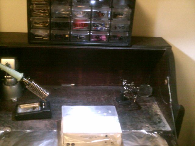 containing the parts:
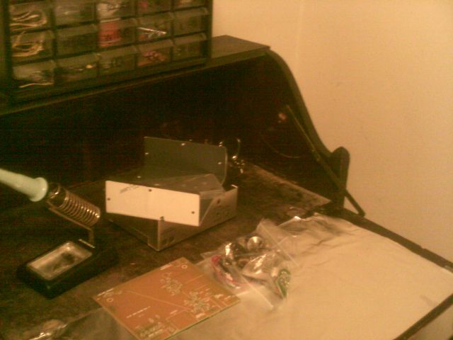 The box also included a piece of paper saying that MFJ has put its manuals online instead of printing them. Found the PDF, and immediately found a problem. The PDF didn't include any of the pictures. No schematic, no PC board view, and (most importantly) no pic of the coil you wind yourself. Was I missing a trick in displaying the PDF, or was it bad?
Emailed MFJ. They responded in a few hours. The PDF was indeed wrong, and they added the pics and re-uploaded.
Wonderful to deal with a small company that WANTS TO PLEASE ITS CUSTOMERS!
Ready for work:
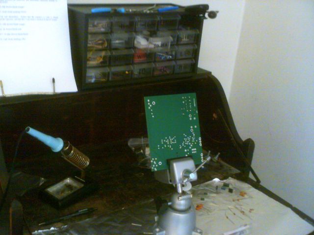 The assembling went smoothly and took about 6 hours spread over three days. EXCEPT:
I had to spend an extra two hours correcting two mistakes that were MY fault. I had switched a 15-ohm resistor (brown-green-black) with a 1M resistor (brown-black-green), and then put one of them in the wrong place when trying to refit. Refitting is hard work, requiring careful use of solderwick and 'prosthetic leads' on the shortened resistor....
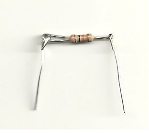 .....but in the end it came out right.
I can partly blame MFJ for making the latter error easier. (Wrong place on refit.) Comparing with the little Pixie that I built last month with NO errors ... The Pixie is much smaller with about the same number of parts. Cramped metropolis vs prairie settlement.
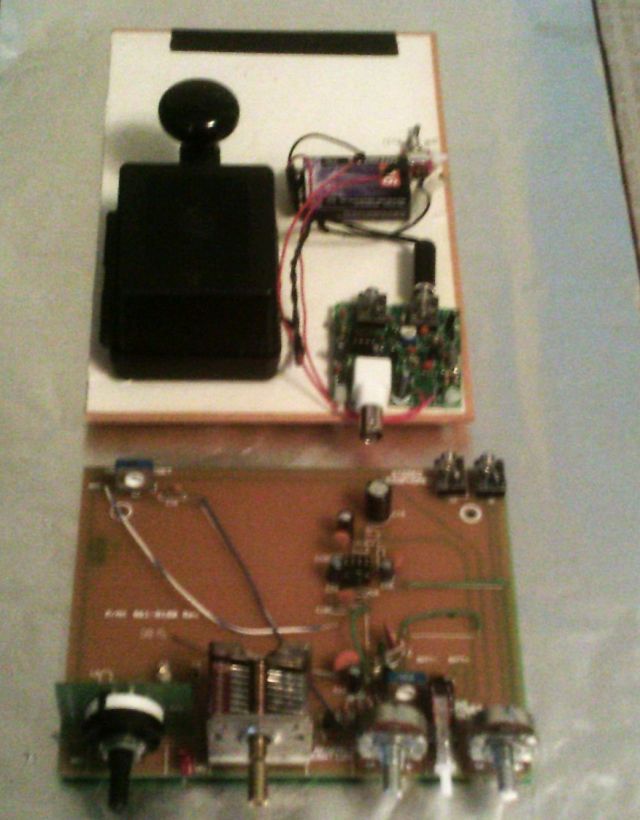 My old eyes should have caused more problems in the urban metropolis, but it was the other way around. I think the difference is in the sequence of placement. Pixie came without instructions, which ALSO may have caused me to work more carefully. Moral hazard. Just a parts list with all Rs first, then all Cs, then all heat-sensitive parts, then the big plugs. This sequence eliminated blockages or coverings. MFJ has you place some large trimmers and lytics before some of the little resistors, which blocks the markings and allows confusion.
Next time I build a kit, I'll use the Pixie sequence. I'll format the parts list as a table in smallest-first order, print it out BIG, place the actual parts ON the right side of the actual paper, then work directly from this parts list / parts bin.
= = = = =
The MFJ worked as soon as I turned it on. Shortwave signals are sparse here, so I had to make my own signal by V-ing the Pixie. Tuning the MFJ without the knobs or dial markings, the V came through in just one spot on the tuning cap. No splatter even at a distance of 3 feet with an open case. And I could get a nice BFO tone on the CW by turning the regen control up, just as it's meant to work.
YAY!
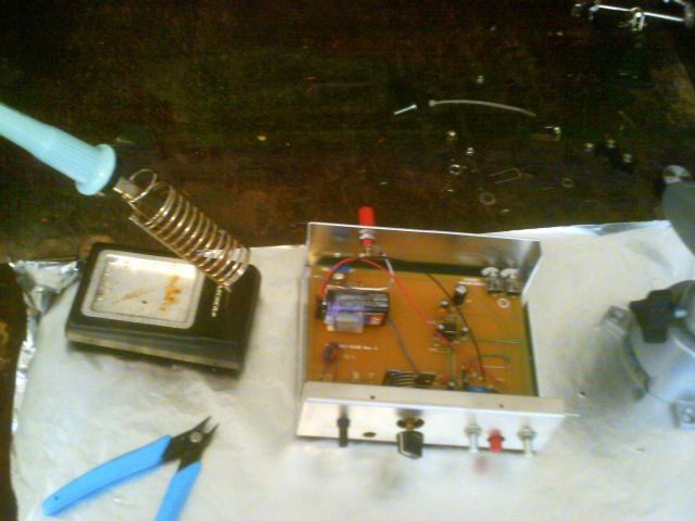 After I verified that something was happening, I put it in the case, making it more stable, and attached a somewhat longer antenna. Then I could hear a ham talking on SSB, and used the regen to BFO the SSB as well. Spokane has poor SW reception, so this isn't going to be a big source of incoming entertainment. That isn't the point anyway. Building and understanding is the point.
[Later, after attaching a 40m whip antenna: Lots of good stuff that I hadn't heard before on other receivers, with emphasis on CW and SSB. I'm starting to think that Spokane isn't so awful for shortwave after all, and I'm also realizing that the house's aluminum siding wasn't really the problem. This receiver simply isn't bothered by power-line noise OR by the computer running in the same room.]
= = = = =
A few inconsistencies in the instructions and lists. Only the last one (8) really matters.
(1) On R3, the schematic says 470 but the parts list, actual parts, and instructions say 10k.
(2) The volume pot is actually 300, not 250 as the manual says.
(3) Instructions for caps are probably a bit too specific for beginners.
For instance: Install C4, .1µF (body marking: 104Z)
The letter on ceramic caps is the percent tolerance. The supplied caps have various letters. This doesn't matter because bypass caps rarely need a precise value; but a beginner could be confused by finding 104M when the instruction says 104Z.
(4) The lugs on the tuning cap don't quite fit in the holes. I had to carefully trim part of the lugs off.
(5) The parts numbering isn't consecutive. The Rs go from 1 to 20, but R10,14,15,16,18 don't actually exist. Apparently these were 'simplified out' over the years. This isn't an inconsistency because the parts, instructions and parts list all agree on which Rs are there; but consecutive numbering would make proofreading and error-checking easier.
(6) L4 is .33 uH on the schematic and .47 uH in real life. Again probably a revision.
(7) Instructions tell you to push the LED into the board "as far as it will go", solder, then bend it forward so it will pop through the hole in front of panel. Can't have both. I went ahead and put it all the way in and left it vertical. It's still visible from the front, even if it doesn't come out of the panel. If you want to bend it, you need to leave it above the board 3/8" or so.
(8) There are three panel-mounting nuts and washers, all the right size for the two pots, but the plastic bandswitch is larger than the pots. The nuts don't fit the bandswitch.
On a hunch, I opened up an old Delco [superhet!] radio that I use as a clock stand. It's unrepairable, so its volume pot will never be turned. Sure enough, the pot nut fits the new plastic bandswitch perfectly!
 Here's the basically finished MFJ saying THANKS to Old Master Delco.
This is Part 1 of a series. Part 2 here, part 3 here.
 .....but in the end it came out right.
I can partly blame MFJ for making the latter error easier. (Wrong place on refit.) Comparing with the little Pixie that I built last month with NO errors ... The Pixie is much smaller with about the same number of parts. Cramped metropolis vs prairie settlement.
 My old eyes should have caused more problems in the urban metropolis, but it was the other way around. I think the difference is in the sequence of placement. Pixie came without instructions, which ALSO may have caused me to work more carefully. Moral hazard. Just a parts list with all Rs first, then all Cs, then all heat-sensitive parts, then the big plugs. This sequence eliminated blockages or coverings. MFJ has you place some large trimmers and lytics before some of the little resistors, which blocks the markings and allows confusion.
Next time I build a kit, I'll use the Pixie sequence. I'll format the parts list as a table in smallest-first order, print it out BIG, place the actual parts ON the right side of the actual paper, then work directly from this parts list / parts bin.
= = = = =
The MFJ worked as soon as I turned it on. Shortwave signals are sparse here, so I had to make my own signal by V-ing the Pixie. Tuning the MFJ without the knobs or dial markings, the V came through in just one spot on the tuning cap. No splatter even at a distance of 3 feet with an open case. And I could get a nice BFO tone on the CW by turning the regen control up, just as it's meant to work.
YAY!
 After I verified that something was happening, I put it in the case, making it more stable, and attached a somewhat longer antenna. Then I could hear a ham talking on SSB, and used the regen to BFO the SSB as well. Spokane has poor SW reception, so this isn't going to be a big source of incoming entertainment. That isn't the point anyway. Building and understanding is the point.
[Later, after attaching a 40m whip antenna: Lots of good stuff that I hadn't heard before on other receivers, with emphasis on CW and SSB. I'm starting to think that Spokane isn't so awful for shortwave after all, and I'm also realizing that the house's aluminum siding wasn't really the problem. This receiver simply isn't bothered by power-line noise OR by the computer running in the same room.]
= = = = =
A few inconsistencies in the instructions and lists. Only the last one (8) really matters.
(1) On R3, the schematic says 470 but the parts list, actual parts, and instructions say 10k.
(2) The volume pot is actually 300, not 250 as the manual says.
(3) Instructions for caps are probably a bit too specific for beginners.
For instance: Install C4, .1µF (body marking: 104Z)
The letter on ceramic caps is the percent tolerance. The supplied caps have various letters. This doesn't matter because bypass caps rarely need a precise value; but a beginner could be confused by finding 104M when the instruction says 104Z.
(4) The lugs on the tuning cap don't quite fit in the holes. I had to carefully trim part of the lugs off.
(5) The parts numbering isn't consecutive. The Rs go from 1 to 20, but R10,14,15,16,18 don't actually exist. Apparently these were 'simplified out' over the years. This isn't an inconsistency because the parts, instructions and parts list all agree on which Rs are there; but consecutive numbering would make proofreading and error-checking easier.
(6) L4 is .33 uH on the schematic and .47 uH in real life. Again probably a revision.
(7) Instructions tell you to push the LED into the board "as far as it will go", solder, then bend it forward so it will pop through the hole in front of panel. Can't have both. I went ahead and put it all the way in and left it vertical. It's still visible from the front, even if it doesn't come out of the panel. If you want to bend it, you need to leave it above the board 3/8" or so.
(8) There are three panel-mounting nuts and washers, all the right size for the two pots, but the plastic bandswitch is larger than the pots. The nuts don't fit the bandswitch.
On a hunch, I opened up an old Delco [superhet!] radio that I use as a clock stand. It's unrepairable, so its volume pot will never be turned. Sure enough, the pot nut fits the new plastic bandswitch perfectly!
 Here's the basically finished MFJ saying THANKS to Old Master Delco.
This is Part 1 of a series. Part 2 here, part 3 here.
Here's the basically finished MFJ saying THANKS to Old Master Delco.
This is Part 1 of a series. Part 2 here, part 3 here.Labels: coot-proofing, defensible spaces, Make or break, new toy
